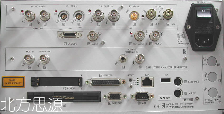
 接口照片
接口照片SN:BN-0158
厂家: W & G
面板接口
0.172 JITTER ANALYZER / GENERATOR MODULE
[30] MOD.IN
[31] DEMOD.OUT
[34][35] WANDER REFERENCE IN
AUXILIARY
[12] [13] 1,5/2Mbit/s
LINE
[14] [15] 1,5...156Mbit/s
[16] 622Mbit/s
[17] [18] OC-1/3/12, STM-1/4
[21] DCC/ECC
[22] CLOCK
[25] REF CLOCK IN
[26] TRIGGER
OTHER
[01] MOUSE
[02] PCMCIA
[03] KEYBOARD
[04] MONITOR
[05] PRINTER
[06] V.24
[07] CONTRAST BLK/W DISPLAY
[08] FLOPPY DRIVE
详细指标 pdf文档
・带有内置内装PC机的模块化结构有能力满足当前和未来测试的需要
・所提供的测试方案SONET,SDH,ATM,DS3,DS1和E4- -E1(PDH)
・基于Microsoft Windows的图形化用户界面“点触”式触措屏使操作更为简便易行
・供自动测试使用的CATS(CVL就用软件测试序列)程序库
・便携式坚固设计,适于现场现场使用
・先进的网络测试
・完善的结果表示方式
・CATS:节省时间的测试序列
技术指标
发生器单元:
・Digital outputs
・Interfaces to Bellcore GR-253,TR-TSY-000499,ANSI T1.102 75Ω coaxial
output,adapter jack selectable from
・Versacon 9 adapter system
・Bit rates and line codes
・DS1......1544kbit/s;B8ZS,AMI,CMI
・DS2......6312kbit/s;B8ZS,CMI
・DS3......44736kbit/s;B3ZS,CMI
・STS-1......51840kbit/s;B3ZS,CMI
・STS-3......155520 kbit/s;CMI
・100Ωbalaced output,Bantam jack
・Bit rate and line codes
・DS1......1544kbit/s;B8ZS,AMI,CMI
・Output pulses
・DS1......DSX-1 compatible
・DS2......retangular
・DS3,STS-1.......HIGH,LOW,DSX-3
・Bit rate offset......±2ppm
・Synchronization to external signals
・via 100Ωbalanced input,Bantam jack:
・Reference clock......1544kHz and 2048kHz
・1544kbit/s(B8ZS)2048kbit/s(HDB)or Receive signal
・Clock outputs
・Clock output at frequency of generator signal,approx.400mV(when terminated
into 75Ω),BNC jack.
・STS-3output signal
・Generation of a STS-3 signal conforming to Bellcore GR-253,ANSI T1.105
・The STS-3signal consists of one internal STS-1 tributary signal with the
remaining two tributaries filled with UNEQ.
・STS-1 output signal
・Generation of a STS-1 signal conforming to Bellcore GR-253,ANSI T1.105
・Mappings
・One selectable STS-1 mapping is included in the basic instrument.Other
mappings can be added as needed.
・Content of the selected tributary:
・Framed or unframed DS1 or DS3 test pattern
・M13 multiplex signal(with M13 MUX/DEMUX option)
・External DS1 or DS3 signal(with D&1 option)
・Test pattern without stuffing bits(bulk signal to O.181)
・Conternt of non-selected tributaries......framed PRBS2047
・The various mappings are described along with the options.
・Generation of pointer actions(figure 1)
・Generation of pointer actions at the STS-1 and VT levels simultaneously.
・Pointer sequences to T1.105.03 with programmable spacing
・Pointer increment/decrement(continuously repeated)
・Single pointer
・Pointer value setting with or without NDF
・Content of TOH and POH bytes
・The content of all bytes with the exception of B1/B2/B3 and H1 to H4 is
programmable with any byte or a user defined byte-sequence p in min in n (p
frames in m frames and the entire sequence repeated n times)can be inserted.
・Bytes E1,E2,F1,F2,and byte groups D1to D3and D4 to D12:
・Transmission of a PRBS with bit error insertion(selectable in signal
structure)
・Insertion of an external data signal(via V.11 interface;also for K1and K2)
・Trace identifier
・J0,J1,J2......programmable 16 byte ASCII serquence with CRC
・J1,J2,additionally.....programmable 64 byte ASCII sequency
・H4 byte......4or 48 byte sequence
・Error insertion
・Error types.......B1,B2,B3parity errors
・frame errors,REI-L,REI-P,bit errors in test pattern,
・BPV(single errors)
・Triggering
・Single error or error ratio......2×0.001to 1×0.0000000001
・for B1,B3,REI-P.......2×0.0001to 1×0.0000000001
・for bit errors......1×0.01to 1×0.0000000001
・Step size for mantissa and exponent.......1
・Alarm generatio
・Dynamic
・Alarm types.......LOF,AIS-L,RDI-L,LOP-P,AIS-P,UNEQ-P,RDI-P,RDIEPP,RDIEPS,RDIEPC,PDI-P
・m alarms in n frames......m=1 to n-1,n(max)=8000 or t1 alarm active t2 alarm
passive.......t1=0 to 60s,t2=0 to 600s
・Static(on/off)
・Alarm types......LOS,LOF,AIS-L,TIM-L,RDI-L,LOP-P,AIS-P,UNEQ-P,PLM-P,TIM-P,RDI-P,RDIEPP,RDIEPS,RDIEPC,PDI-P
・DS1,DS2 and DS3 output signals
・Signal structures
・Unframed test pattern
・Framed test pattern(only DS1,DS3)
・DS1 frame sructure.......SF,ESF
・DS3 frame structure.......M13,Cparity
・Error insertion
・Bit errors in test pattern......error rate,single error
・BPV......single error
・DS1 Fbit(LOF)......single error,2 in 4,2 in 5,2 in 6
・CRC-6(ESF)......single error,error rate
・DS3 F bit(LOF)......single error,2 in 2,2 in 3,3 in 3,3 in 15,3 in 16,3 in 17
・Parity,FEBE(C parity)......single error,error rate
・Error rate......1×0.00000001 to 2×0.001
・Alarm insertion
・DS1......LOF,AIS,YELLOW
・DS3......LOF,AIS,YELLOW,IDLE
・Test patterns
・Pseudo-random bit serquences
・PRBS
・Programmable word
・Length ......16bits
・接收机单元
・Digital inputs
・Interfaces to ......Bellcore GR-253,TR-TSY-000499,ANS T1.102 75Ω coaxial
input;adapter jack selecable from
・Versacon 9 adapter system
・Bit rates and line codes
・DS1......1544 kbit/s;B8ZS,AMI,CMI
・DS2......6312kbit/s;B8ZS,CMI
・DS3......47736 kbit/s;B3ZS,CMI
・STS-1......51840kbit/s;B3ZS,CMI
・STS-3......155520kbit/s;CMI
・100Ωbalaced input,Bantam jack
・Bit rate and line codes
・DS1......1544kbit/s;B8ZS,AMI,CMI
・Input levels
・DS1.......DSX-1 compatible
・DS3,STS-1......HIGH,LOW,DSX-3
・Clock recovery pulling range......±500ppm
・Selectable input gain,CMI coded.......15 to 23dB
・B3ZS,B8ZS,HDB3,AMI coded......15 to 26dB
・Selectable adaptiveequalizers for DS3,STS-1......45ft
・Monitor input for STS-3 and STS-12 NRZ signals
・See ANT-20 Optical Interfaces data sheet fordetails.
・STS-3receive signal
・(for signal structure,see under generator unit)
・The ANT-20 demultiplexes one selectable STS-tributary from STS-3 and feeds it
to the internal processor for evaluation.
・STS-1,DS1 and DS3 receive signals
・Signal structures as for generator unit
・Trigger output
・75Ω BNC connector,HCMOS signal level
・Pulse output for received bit errors,transmit frmae trigger,transmit paatern
trigger or 2048kHz reference clock
・自动模式
・Autoconfiguration
・Automatically sets the ANT-20 to the input signal.The routine searches at the
electrical and optical interfaces for the presence of standard asynchronous and
STS-N/OC-N signals(GR-253,ANSI T1.102)and the payload conternts in channel1.
・Automatic SCAN function
・The SCAN function permits sequential testing of all VT1.5 or VT2 channels in a
SONET signal.The ANT-20 receiver checks for alarms in the receive signal ,the
SONET stucture and all channels and for synchronization of the selected test
pattern entered in a matrix.the generator runs simultaneously and can be used to
stimulate the device under test.
・Automatic TROUBLE SCAN function(figure2)
・The TROUBLE SCAN function permits sequenctial testing of all VT1.5 or VT2
channels in a SONET signal.The ANT-20 receiver checks for alarms in the receive
signal ,the SONET structure and all channels.The results(OK/not OK)for each
channel are entered in matrix.Adetailed alarm history can be displayed by
selecting a channel from the matrix.Only the receive channels are altered suring
a TROUBLE SCAN.
・Automatic SEARCH function
・Channel shifts in the payload may occur when measuring complex network
elements,depending on the configuration of the device under test.The SEARCH
function permits rapid automatic location of the test channel(VT1.5 or VT2 with
defined PRBS)in the payload of a SONET signal,The ANT-20 receiver checks for
alarms in the receive signal,the SONET structure and all channels and for
synchronization of the selected test pattern in all channels.The results (OK/not
OK)for each channel are entered in a matrix.An OK result indicates that the
corresponding channel contains the signal searched for.Only the receive channels
are altered during a SEARCH.
・测量类型
・Error measurements
・Error types......B1,B2,B3 parity errors frame errors,REI-L,REI-P,bit errors in
test pattern,BPV
・Additionally,for
・DS1......CRC errors
・DS3......parity errors,C parity errors,FEBE
・Error Count,Error Rate,Intermediate Errors
・Performance analysis
・ES,SES,EFS,SEFS,UASare evaluated
・In-service measurements(ISM)
・Simultaeous ISM of the near-end and far-end of a selected path
・Near-end......B1,B2,B3,BIP-V,CRC-6
・Far-end.......REI-L,REI-P,REI-V
・DS1,DS3 events......F bit,parity,FEBE,C parity
・Out-of-service measurements(OOS)
・OOS evaluation using bit errors in test pattern
・Analysis of STS-1 and VTpointer actions(figue3)
・Display of
・Number of pointer operations:Increment,Decrement,Sum(Increment+Decrement).
・Difference(Increment-Decrement)
・Pointer value
・Clock rquency measurement
・The deviation of the input signal clock frequency from the nominal frequency
is displayed in ppm.
・Delay measurement
・Dlay measurements are used for aligning satellite hops and testing the maximum
permitted delay times for storage exchange and cross-connect systems and for
checking the loop circuits in regenerators.
・The ANT-20 measures the time taken to transmit the test pattern from the
generator through the section under test and back to the receiver.the
measurement is made on the test patterns in a selected channel,or in the
tributaries(SONET;bulk signal or asynchronous),or on the selected channel of the
lowest hierarchy level of asynchronous multiplex systems.To avoid ambiguities in
the measurement,two measurement times are provided.
・Measurementrange
・Bit rates from 34 to 155Mbit/s......1μsto 1s
・Bit rate 1.5Mbit/s......10μs to 5s
・Alarm detection
・All alarms are evaluated and displayed in parallel
・Alarm types......AIS-L,RDI-L,AIS-P,LOP-P,NDF-P,RDI-P,UNEQ-P,TIM-P,PLM-P
・Additionally,for DS1,DS3.......LSS,AIS,RAI(YELLOW)IDLE(DS3)
・TOH and POH evaluation
・Display of complete TOH and POH,e.g.interpretation of APS information in K1
and K2
・For the bytesE1,E2,F1,F2 and byte groups D1 to D3 and D4 to D12:
・BERT using test pattern form the generator unit
・Output of the data signal via the V.11 interface(also for K1,K2)
・For the Trace ldentifier
・J0......display of 1 byte or 16-byte ASCII seqrence
・J1,J2.......display of 16 or 64-byte ASCII sequence
・Measurement interval
・Variable......1 second to 99days
・Measurement start...... manual or automatic timer(user setting)
・Measurement stop......manual or automatic timer(user setting)
・Memory for errors,pointer operations and alarms
・Reslution of error events and pointers......1s
・Alarm resolution......100ms
・Memory capacity......up to 1million entries(approx.100days at 7entries per
minute)
・Off-line analysis software
・The software runs on standard PCs and permits comprehen-sive analysis of
stored ANT-20rsults.After loading the results,the ANT-20 settings surng the
measurement and the stored results can be accessed.
・Zoom and filter functions allow detailed evaluations.The proceesed results can
be exported in CSV format for importing into other programs such as Excel or
Winword for producing documentation.
・结果显示及仪器操作
・Numerical display
・Display of absolute and relative values for all error types
・Intermediate results......every 1s to 99min
・Graphical display(histogram)(figure 4)
・Display of errors,pointer operations/values and alarms as bargraphs vs.time
・Units,time axis......seconds,minutes,15minutes,hours,days
・Tabular display
・Display of all alarm and error events with time stamp
・Result printout
・ANT-20 supports a variely of dot-matrix,indjet and laser printers(Windows
Print Manager)
・Printer interfaces
・Serial......V.24/RS 232
・Parallel......Centronics/EPP/IEEE P1284
・Result export
・Results are stored in a database and can be processed using standard PC
softawre
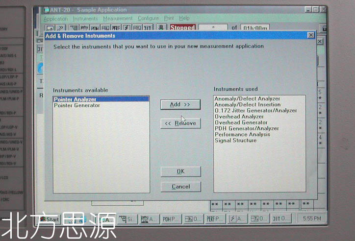
・Instrument operation
・ANT-20 is operated using the standard Microsoft Windows(TM)graphical user
interface.Operation is menu-controlled using the trackball or optional
touchscreen.A mouse can also be connected if desired.
・Application selection and storage
・ANT-20 includes and applications library to which customer-specific
applications can be added.
・All opplications are stored internally and can be copied to any other ANT-20
via floppy disk.
・Easy to use filter functions allow quick selection of the desired application.
・Display
・Two large display screens are available for the ANT-20:
・Monochrome LCD or color TFT.
・Monochrome LCD......9.5",16gray scales
・Resolution......640×480 pixels(VGA standard)
・Color TFT screen......9.5",256 colors
・Resolution......640×480pixels(VGS standard)
・Built-in PC
・ANT-20 uses a Pentium PC as internal controller so that standard PC
applications can also be run on the instrument.
・RAM capacity......16MB
・Floppy drive......3.5",1.44MB
・Hard disk drive......1GB(minimum)
・Keyboard
・Full keyboard for text input,extended PC applications and future
requirements.The keyboard is protected by a fold back cover.An additional
cnnector is proviede for a standard PC keyboard.
・External display connector
・Simultaneous display with built-in screen
・Interface......VGA standard
・PCMCIA interface
・Type......PCMCIA2.1typesI,IIand III
・The PCMCIA interface provides acces to GPIB,LANs,etc.iva adapter cards.
・Power outage function
・In the event of an AC line power faliure during a measurement,ANT-20 saves all
data.As soon as the AC line voltage is reestablished,the AC line voltage is
reestablished,the measurement is resumed.Previous rsults are retained and the
time of the power failure is recorded along with other events.
咨询电话: 132- 4173- 5460 , 邮箱: 52634729@QQ.com